Soldering PCB Components Task

This task will require you to hand-solder a number of components onto a PCB, simulating the process of building a design called LoopOne.

LoopOne

LoopOne is an open-source design that aims to alleviate thermal discomfort among wheelchair users. It works by circulating water through a tube in the wheelchair’s cushion for a cooling or heating effect which the user can control as required. In addition to improving the user’s comfort, thermally regulating the seat temperature can minimise the risk of pressure sores.

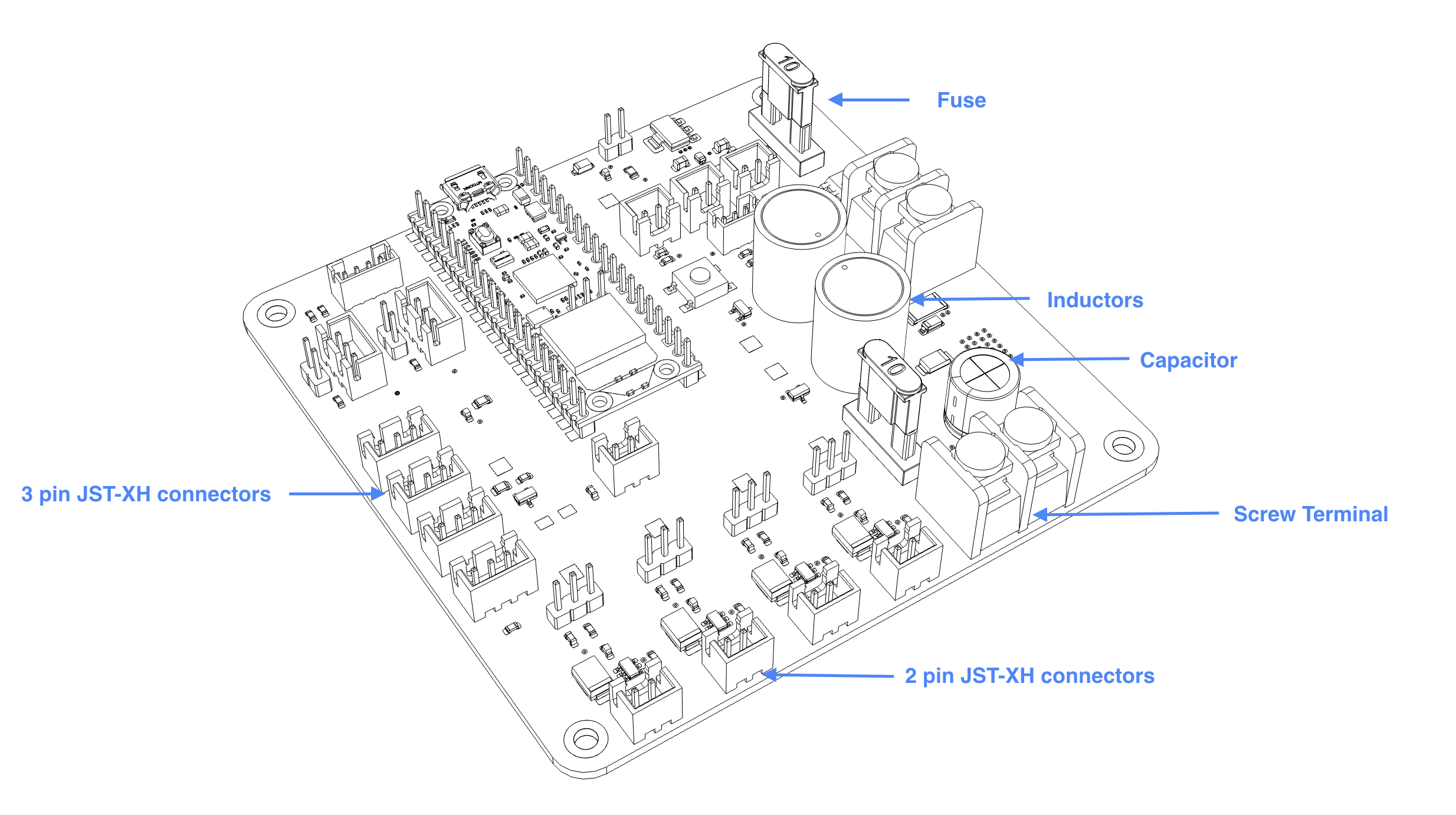
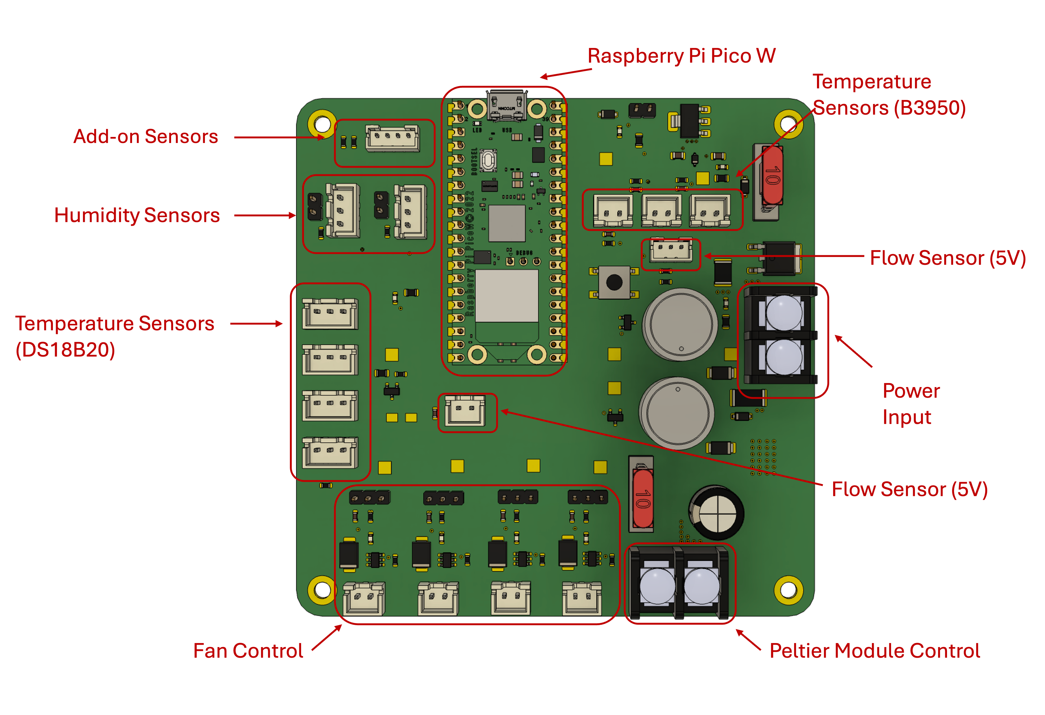
I’ve designed a custom circuit board (PCB) which handles all necessary functions for this design:

  • Heating and cooling the water (this is done through a small component called a Peltier module)
  • Circulating the water (this is done through a water pump)
  • Sensing water flow (this is a safety measure to ensure any bends in the tube do not increase pressure and put unnecessary strain on the water pump)
  • Sensing temperature and humidity (this allows us to monitor multiple points for temperature and humidity, which in turn allows the user to set up custom settings to suit their needs)
  • Connecting fans (this is an optional add-on where users can choose to add air fans to either blow air through the cushion or toward the user in hot/humid weather)
  • Connecting additional sensors (this takes the form of an I2C port, which DIY-minded users can use to to incorporate additional sensors of choice)

Top down view of the Loop One PCB with various functionalities of the board annotated. Top down view of the Loop One PCB with various functionalities of the board annotated.

Why do I need to solder?

In the spirit of keeping this design as financially accessible as possible, we are testing whether it would be possible for those with ‘making’ skills to hand-solder larger components to a PCB themselves. This results in a significantly lower cost compared to purchasing a PCB with all required components pre-assembled by the manufacturer.

Subsections of Soldering PCB Components Task

A refresher (or lesson!) on soldering

Tools and Parts Needed:

  • Soldering iron
  • Soldering wire
  • Tip cleaner
  • Flux
  • Tinner
  • Prototyping board
  • Red cable
  • Black cable

Learning Task Instructions:

  1. Assemble the tools and components needed for this task
  2. Identify the prototyping board (shown below)
  3. Affix the cable given to you through the prototyping board
  4. Apply some flux and use the soldering iron and wire to solder the cable to the board
  5. Power off the iron, securely set aside and check the connection, here’s a useful image by Adafruit that can help you judge the quality of your solder joints.

Image by Adafruit displaying different solder joints side by side. Image by Adafruit displaying different solder joints side by side.

Soldering the PCB

Have you done the required reading? It’s here

Loop One PCB with components labelled Loop One PCB with components labelled

Tools and Parts Needed:

  • Soldering Iron
  • Soldering Wire
  • Tip Cleaner
  • Flux
  • Tinner
  • PCB
  • Screw Terminal (black, 2-pin)
  • Inductor (grey cylinder, 2-pin)
  • JST-XH connectors
  • Soldering helper (choose from 3D printed jig, masking tape, or “helping hands”)

Soldering Task Instructions:

  1. Assemble the tools and components needed for soldering
  2. Prepare PCB for soldering with soldering setup of choice.
  3. Affix the screw terminal on the PCB with a “helping hand” or with some masking tape. Be mindful of its orientation.
    Note

    If you are using the 3D printed soldering jig, you want to start with the shortest component we will be soldering today, the JST-XH connectors.

  4. Verify the orientation and solder the component to the PCB.
  5. Now try to solder more components.