DIY-AT Research
This site contains information on the prototypes and studies that make up part of my PhD research. For the DIY-AT workshop for participants with making experience go here.
This site contains information on the prototypes and studies that make up part of my PhD research. For the DIY-AT workshop for participants with making experience go here.
This workshop is part of my PhD research in DIY assistive technology (DIY-AT). Following an interview process with multiple wheelchair users, seating comfort of manual chairs was identified as a common need. I have since designed some prototypes that are meant to be DIY (“do it yourself”). Getting these prototypes to finished designs, I need to better understand what format they need to be distributed at. Are they better served as a simple “DIY” kit? Are they simple enough to source and assemble individually by users?
The aim of this workshop is to understand how users with making experience, interact with my prototypes. Through your experience assembling this prototype we can hopefully identify any design weaknesses or different ways of doing things.
Please make sure to read through the participant information below and then complete the consent form which can be found here. Upon completion alert the researcher running the session.
This workshop is being conducted as part of a UCL PhD degree. This project has been approved by the UCL Ethics Board, Project ID: UCLIC_2024_003_Rogers. All data will be handled in accordance with the General Data Protection Regulations (GDPR) and will be anonymised. If you decide to share contact information for further studies, this will be kept separate from the data collected. Only the researcher running the session will have access to the data. You will not be identifiable in any publications that may arise from this data.
Invitation: You are being invited to take part in a research project. Before you decide it is important for you to understand why the research is being done and what participation will involve. Please take time to read the following information carefully and ask us if there is anything that is not clear or if you would like more information. Take time to decide whether or not you wish to take part.
What is the project’s purpose? The purpose of this workshop is to observe wheelchair users with making experience as they build DIY assistive technology (DIY-AT) and to understand what part of the design, dissemination or making process can be improved and how.
Why have I been chosen? You have been chosen because you expressed a willingness to participate in this study and meet the inclusion criteria of being an adult wheelchair user with previous making experience.
Do I have to take part? Taking part in the study is entirely voluntary. If you decide to take part, you will receive this information sheet by email and will be asked to complete the consent form below prior to the beginning of the workshop. You can withdraw at any time without giving a reason.
What will happen to me if I take part? You will be asked to participate in an in-person workshop where you will follow web-based instructions to perform a series of making-related tasks, namely sourcing components for a DIY project, soldering, coding, and 3D printing. The primary researcher and two other participants will be present during the study and will be in conversation with you as you proceed through the tasks.
Will I be recorded and how will the recorded media be used? The workshop will be video-recorded so that the researcher can analyse each participant’s experience and identify any common themes. An anonymised transcript will be created based on the audio recording and pictures will be selected from the video. The pictures will be used for publications and presentations. The video will then be deleted.
What are the possible disadvantages and risks of taking part? This research poses no risk greater than that which you would encounter during your other making activities. If you wish to skip any tasks, you are free to do so without it affecting your participation in the rest of the study and any compensation you may be eligible for.
What are the possible benefits of taking part? By participating in this study, you help us improve the process of DIY-AT design so that users of varying making expertise can have access to DIY assistive technology. Additionally, you may learn a new making skill from the tasks you have to complete.
What if something goes wrong? If you wish to raise any issues relating to this research, please contact Professor Yvonne Rogers who is the Principal Researcher on the project, at y.rogers@ucl.ac.uk. You can also contact the Chair of the UCL Research Ethics Committee, at ethics@ucl.ac.uk, should you feel your concern has not been handled to your satisfaction (e.g. by the PR or the supervisor).
Will my taking part in this project be kept confidential? All the audio information that we collect from you during the course of the research will be transcribed and anonymised. The audio will then be permanently deleted. It will not be possible to identify you in pictures included in any ensuing reports or publications as faces will be blurred.
Are there limits to this confidentiality? Please note that every effort will be made to keep your information confidential and to present it in an anonymised format. All personal data will be immediately decoupled from any responses provided. However, you should also note that the nature of your responses – if specific to your studies or work – may mean that you can be indirectly identified from the responses you provide. Please note that confidentiality will also be maintained as far as it is possible, unless during the conversation the researcher hears anything which makes them worried that someone might be in danger of harm, the researcher might have to inform relevant agencies of this.
What will happen to the results of the research project? The workshop transcript, and experiences of the participants will be processed and included in the researcher’s PhD thesis, and possibly an academic publication. The outcome of this workshop will help improve how DIY-AT is designed for makers of all expertise levels.
Who is organising and funding the research? This PhD research is funded by the Department of Computer Science at University College London (UCL).
Thank you for reading this information sheet and for considering taking part in this research study.
Please make sure to complete the consent form
| Item Name | Description | Quantity | Link 1 | Link 2 |
|---|---|---|---|---|
| eSUN TPE 1kg | For very small chairs 1 roll might be enough but 2 will ensure you have enough material in case a part fails. | 2 | Amazon.co.uk | 3djake.uk |
Apart from the above you will of course need a 3D printer capable of printing flexible materials like TPU.
| Item Name | Description | Quantity | Link 1 | Link 2 |
|---|---|---|---|---|
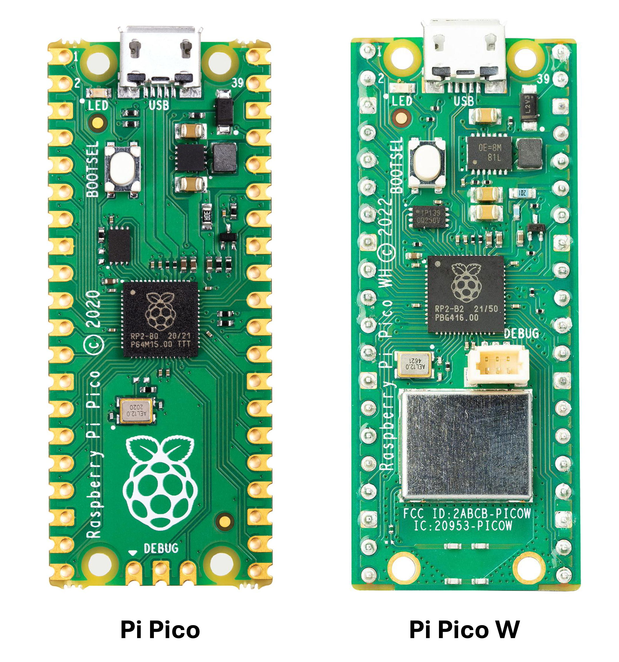
| Raspberry Pi Pico WH | The Pico WH variant includes headers, otherwise you can get a Pico W and solder the headers yourself | 1 | The Pi Hut | Pimoroni |
| JST-XH 2-pin connectors | Links include multiple connectors, you need 8 connectors. | 8 | The Pi Hut | Digikey |
| B3950 Thermistors | Max of 3, these come with the appropriate connectors | 3 | Aliexpress | Amazon.co.uk |
| DS18B20 Thermistors | Max of 4, these will need to be terminated with 3-pin JST-XH connectors | 4 | Amazon.co.uk | Aliexpress |
| Peltier Cooler | Used as the heating/cooling element | 1 | Amazon.co.uk | Aliexpress |
This task will require you to hand-solder a number of components onto a PCB, simulating the process of building a design called LoopOne.
LoopOne is an open-source design that aims to alleviate thermal discomfort among wheelchair users. It works by circulating water through a tube in the wheelchair’s cushion for a cooling or heating effect which the user can control as required. In addition to improving the user’s comfort, thermally regulating the seat temperature can minimise the risk of pressure sores.
I’ve designed a custom circuit board (PCB) which handles all necessary functions for this design:
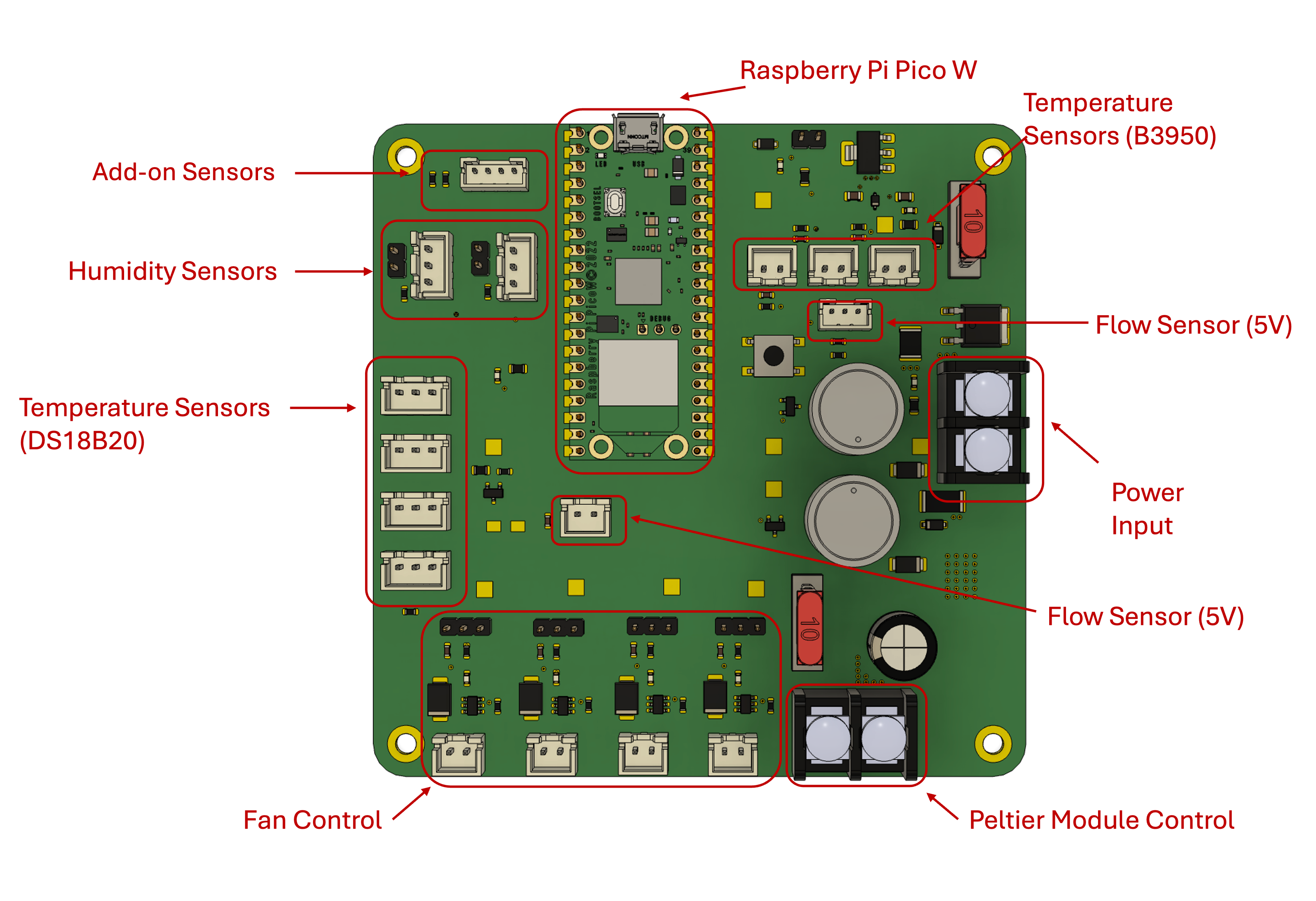
In the spirit of keeping this design as financially accessible as possible, we are testing whether it would be possible for those with ‘making’ skills to hand-solder larger components to a PCB themselves. This results in a significantly lower cost compared to purchasing a PCB with all required components pre-assembled by the manufacturer.

Have you done the required reading? It’s here
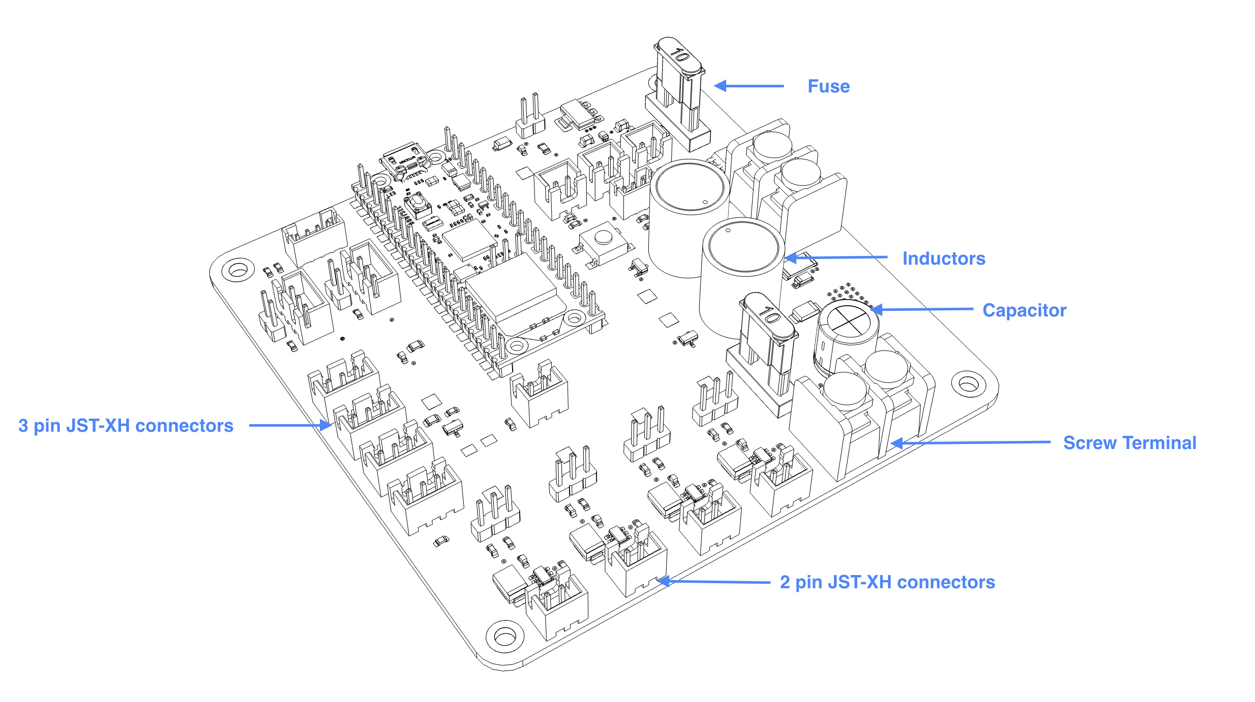
If you are using the 3D printed soldering jig, you want to start with the shortest component we will be soldering today, the JST-XH connectors.
Make sure you drag the CircuitPython file and not the firmware.
print(f"Temperature: {temp:.1f}°C").OpenCushion is a project that allows users to customise and 3D print wheelchair cushions using flexible materials, with the aim of evenly distributing pressure and minimising discomfort and the risk of pressure sores. The design is essentially a lattice of varying density, with areas that are subject to high pressure using a lower density lattice and vice versa. As these cushions can be made with most standard consumer-level 3D printers, they can be more affordable as well as geographically and financially accessible.
Compared to purchasing a cushion from a shop, 3D printing one is probably outside of most people’s comfort zone. Though it’s easier than ever to access a 3D printer, with many hobbyists owning one and printers generally available in most makerspaces, the process may still seem daunting for inexperienced makers or anyone not quite confident enough to troubleshoot or resolve any issues. For this reason, we are asking participants to configure and begin a print of their personalised 3D printed cushion.
I have come up with three ways in which we can create personalised cushions:
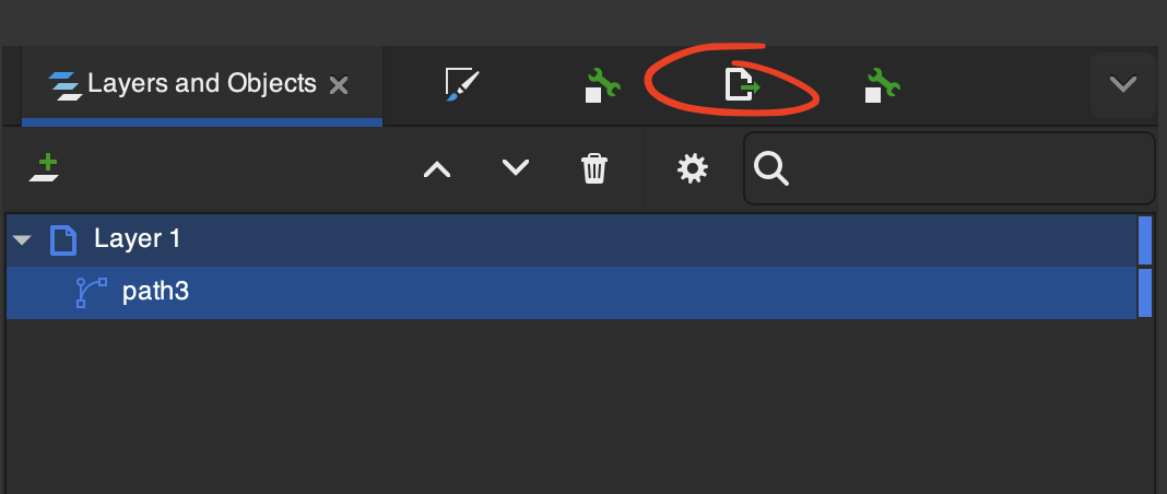
This method takes advantage of a ‘modifier geometry’ feature available in some slicers including Prusaslicer. This allows us to introduce 3D shapes which can interact with the 3D model to modify settings like speed, temperature or line widths. In addition to standard shapes like cubes and cylinders, the modifier geometry feature can also work with SVG files, which we can shape any way we need. If we look at a pressure map like the one below, we can split pressure values into areas and assign different densities to each one. If we can create SVG drawings of each area we can overlay them over our cushion 3D model as modifier geometry and create cushions that go some way toward distributing pressure. This approach is not personalised but is a step forward in improving comfort over standard cushions.
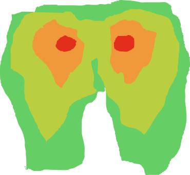
A simplified pressure map example. Usually there are more areas.
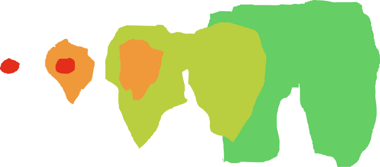
An ’exploded’ view of the pressure map ‘area’ stack.
The rules on creating a curved line apply to the last one as well. So if you need a curve, Left-Click and hold.